Coupled Compass Oscillations
Jalves S. Figueira, Federal Technological University of Paraná, PR, Brazil
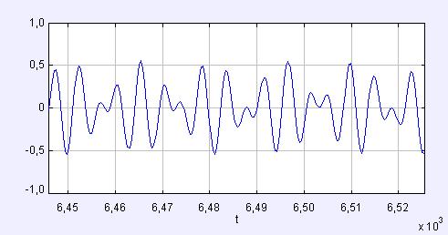
| In this work we present the second in a series of classroom experiments using small compasses. In the first experiment Damping of a Compass Video Analysis Activity we analyzed the damped oscillations of a magnetic compass needle in water, oil and air (Fig. 1). |
|
 |
 |
| Fig.
1 Angular displacement and Fourier Spectrum of an oscillating compass needle in air. |
|
|
In this experiment we will explore the behavior of a pair of loosely coupled compass needles in air with little damping. The needles are far enough apart that the magnetic interaction between their magnetic dipoles is much weaker than their interaction with the Earth's magnetic field. The video file BeatsCompass.flv shows that the coupled oscillations result in beats. When one compass is momentarily at rest, the other oscillates with maximum amplitude. |
|
|
|
|
Tracker Experiment |
|
1. Use the EJS simulation Coupled Oscillators and Normal Modes Model from comPADRE and try to produce beats similar to those shown on the left in Fig. 2. Note that energy is conserved in the simulation. |
|
 |
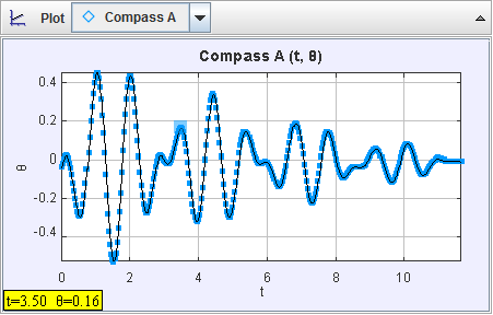 |
Fig. 2 Displacement versus time for the coupled spring-mass model and the coupled compasses video. In the model energy is conserved. |
|
|
2. Determine the harmonic frequency 3. Using the damping constant obtained in the first experiment
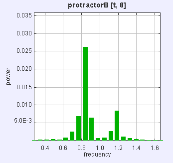
(Fig. 1) and the modulation frequency 4. Determine the normal mode frequencies of oscillation using the Data Tool (Fig. 4). 5. Compare the frequency spectrum of a simple pendulum with the spectrum of the coupled oscillations (normal modes). Why are they not the same? This difference is a characteristic of coupling. |
|
 |
|
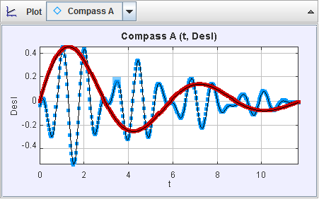
Fig.
3 The red curve describes the modulation result of the superposition
of normal modes of two coupled compasses. |
|
  |
|
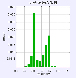
Fig. 4
Normal mode of a Coupled Compass. Compass B on the left and Compass A on the
right. |
|
| The video BeatsCompass.flv was produced
in such a way that the oscillations of the magnetic needle resulted
in superpositions of the normal modes.
Try to produce your own videos with different beat frequencies
and/or normal modes of oscillation. |
|
|
|
|
References |
|
Michael J. Moloneya. Coupled oscillations in suspended magnets, Am. J. Phys., Vol. 76, No. 2 (Feb 2008). Lee, Chan. http://ilyam.org/kypt/Coupled_Compasses.pdf. B. Lunk and R. Beichner. Exploring Magnetic Fields with a Compass, Phys. Teach. 49, 45-48 (Jan 2011). R. Feynman, R. Leighton and M. Sands. The Feynman Lectures on Physics, Vol. I (Addison-Wesley, 1963). |
|